Today I want to show you a 220 volts power inverter circuit. Which it is easy and small size. Because use NE555 and MOSFET as main.
This circuit I experiment it work well,When use source is 12V battery will have output of 100 watts.
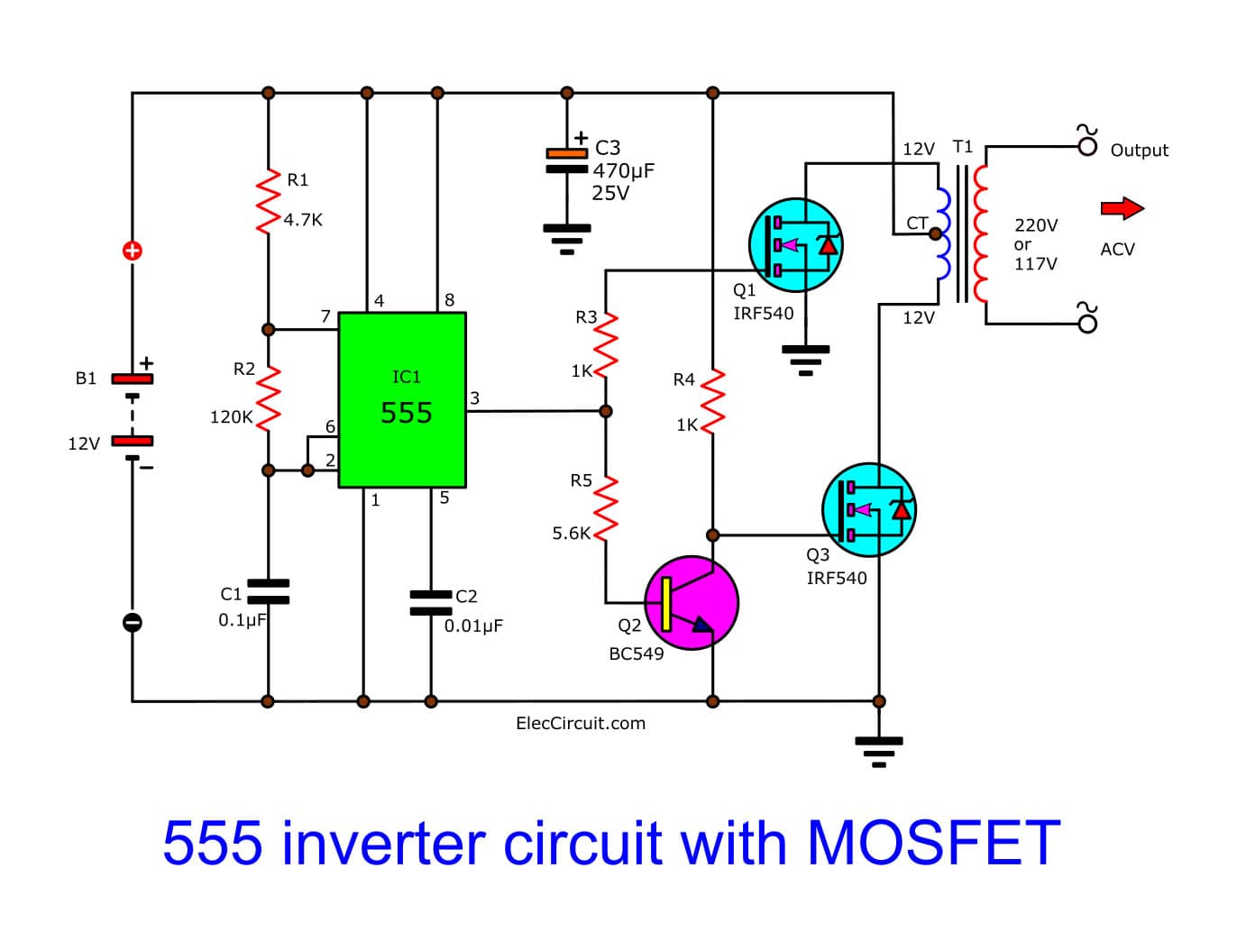
In the Figure 1 is completely circuit diagram of this project. I use IC-NE555 timer is a square wave frequency generator output of 50Hz. The frequency is determined with R2-resistor and C1-capacitor which we set is 50Hz output. Then we use both N-type Mosfet IRF540 (Q2,Q3) as Driver a transformer coil (primary winding). The current of Pin 3 of IC1 will flow two ways, first through R3 to gate of Q2 and, second ways will flow to Q1-transistor BC549 as inverter logic form to reverse signal difference first ways. Next current flow to gate of Q3 to also dirver the transformer. Them cause have AC voltage of 220V to 250V as voltage of battery source 12V to 14.4V.
Figure1
-The transformer I use 2A current and 12V input at output power more than 100 watts.
-I selected IRF540 number because it cheaper and can use for N CHANNEL POWER MOSFET, 100V, 27A, TO-220 easy to mounting on heatsink and easy to use than power transistor. we can use smaller heatsink than a transistor, it not too heat.
How to builds and application
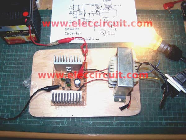
This projects I assemble components on an universal PCB board. As Figure 2 while it operated will a little hot so use enough heatsink.
Figure 2 note: The electrolytic capacitors is 470uf 50V. I put it to filter smooth current. It do not need, if you use 12V battery 10Ah because it is stable power current source.
Then inspect circuit for error. Please watch video below.
We test it with 100 watt at output, then apply 12V battery source.Volts battery less reduce and Lamp glow while AC voltage output is 190V. as source drop. and We check wavefrom is square wave as show on scope.
Note:
Ideally if you need fully 100watts output.
You need you 8A transformer because input watts = output watts = 100watts
Thus primary coil voltage of transformer is 12V at 100watts
Current input = 8A of transformer.
If its not working
I feel uneasy If you build this project It does not work.
First, you need to review well before the pin of the IC, resistors, capacitors And the important is to connect the MOSFET.
View the IRF540 legs use it properly.
Second, should not connect the power cord to the transformer and mosfet.
, and check it frequently generator of IC-555 pin 3 before may be use voltmeter measure voltage across pin 3 and ground.
or use surely oscilloscope to watch waveform. subhajit mondal .......9547380947
I don’t know u call me at 9836160219
Today, there have been 3 visitors (4 hits) on this page!